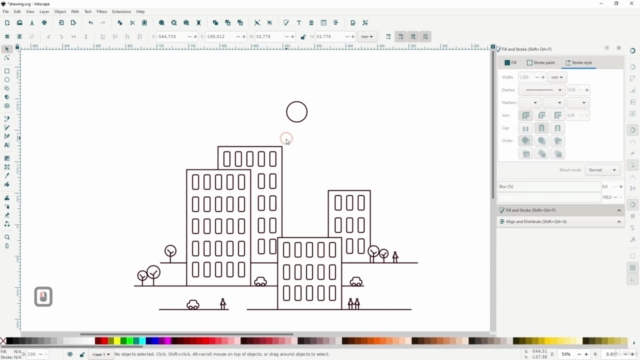

- How modify an imported patent drawing with inkscape. how to#
- How modify an imported patent drawing with inkscape. archive#
I don’t think (but there is zero documentation that I can find on what is and isn’t supported except additive and subtractive paths of which there should be only one being implied but not stated) on what is or isn’t supported. Your tests indicate much of that may not be true though. Reviewing previous posts, the theory was that the same path needed to be in all two or three groups (board with the path id boardoutline, silkscreen (with fill and stroke reversed) and optionally silkscreen0 for the bottom layer (although I don’t know why either silk is needed).
How modify an imported patent drawing with inkscape. how to#
I remember seeing a reference to “look at this example file for how to do this”, so I’ll try and find that and look at the example file to see if that tells me anything.Įdit: I’m admitting defeat, I can’t make this work at all. I’ll continue poking at this and see if I can figure anything out. However, using the Menubar|”Layer>Move_Selection_to Layer” did work to properly save.Īs well Fritzing is reporting no cutouts detected, but is obviously creating the cutouts which is odd. They Temporarily looked correctly Indented but, it was only a ‘momentary’ thing that was not saved. NOTE: Perhaps an issue Only with Mac/OSX but, I noticed the Layers were not always being properly exported in the Inkscape svg.ĭigging into it, I discovered that, ‘Dragging’ to move the layers via the XML panel would not work. Shapes like elipse’s also require Path’ing. The Large and Tall-Skinny Rectangles did Not need to be Path’d but the Small Rectangles Did Require Path’ing (with or without radius corners). The issue seems to be related to: Size of the shape. The “ Yes” is: making the small Rectangles with, or without Radius’d corners into a Path. The “ No” is: when making small Rectangles with, or without Radius’d corners. I wanted to see if repeating the “Simplified” approach when using Inkscape would work as well as when using Gravit.


Also shows up correctly in a Geber Viewer… The Gerber with All the cutouts (and board shape) easily imported into CopperCam (for creating CNC Gcode). In fact, it will work with only a board>boardoutline layer!īelow shows the various elements in Gravit, Fritzing and the exported Gerber Contour file. I want to underscore: No Paths, No Difference, No Subtraction… Proximity to other elements no problems!! Silkscreen worked too Loading the file into Fritzing for the PCB resulted in a ‘Magical’ outcome!Īll elements intended as Cutouts worked including those with tiny features such as Rectangle-Width = 1px and Radius of 0.25px. NOTE: the one ‘Path’ item shown in the Layer panel is a ‘Freehand’ drawn Path (not an element converted into a Path). I simply created the elements and exported as SVG. I did NOT do any Boolean (diff, subtract…) or Pathing. I created a new SVG (using Gravit) that has the recommended Layers (silkscreen, board and boardoutline). Then, exporting an SVG image from Fritzing, revealed the exported file gets updated to include a “boardoutline” layer. Loading a very basic SVG (with my Hand-coded svg (noted in my replies to this post). However, no matter how it’s elements are crafted, differenced, subtracted or path’d, it never consistently worked (for me). I read the SVG1.2 specification to better understand what Fritzing wants - Here’s my take on it:Īfter reading Fritzing info and importing & exporting many SVG’s into/from Fritzing to gain understanding, I discovered some ‘Magic’ that seems to work perfectly well, repeatedly!įritzing info suggests using a Layer called “boardoutline” for cutouts. Summary: A simple way to make the Board with Cutouts (and silkscreen) that appears to play well with Fritzing. This converts the triangle / polygon mesh from an STL file into SVG paths, shading them based on their angle away from the Z axis, and displaying in Z order based on the centre point of each polygon.I Discovered Some ‘ Magic’ regarding making the Board’s SVG
How modify an imported patent drawing with inkscape. archive#
Sent from the OpenSCAD mailing list archive at. If you want a different angle, you'll need to pre-rotate the model before creating the STL file.Īnd here's the image put through my converter script, with fill and stroke modified in Inkscape to be B+W: To simplify the code, it assumes that the viewpoint is from directly above, with no perspective transformations (i.e. Some cleanup may be required due to triangles where the centre point doesn't match the ideal print order.
:max_bytes(150000):strip_icc()/004-export-graphics-from-inkscape-1701894-3b720b3390b74a479483698e616d6c15.jpg)
This converts the triangle / polygon mesh from an STL file into SVG paths, shading them based on their angle away from the Z axis, and displaying in Z order based on the centre point of each polygon. Just in case it helps, I've created an STL to SVG perl script:


 0 kommentar(er)
